GREETINGS!!
Today we will go through the refresher of using CAD fusion 360. In today’s lesson we were refreshed on how to make a keyring. There was an instructional video that was given to us to be used as a reference.
After opening the app, firstly, we will have to select and create a sketch by clicking on the icon circled below. We will then have to select a plane.
We will then have to click on the “2-point rectangle” icon at the top and fill in the numbers, 65mm as the length of the rectangle and 25mm as the breadth, as shown below.
Select the “offset” option that is circled below, and click on the outline of the rectangle. Offset the rectangle by 2mm. As shown in the diagram.
Moving on, click on “fillet” and select all the 4 outer corners of the rectangle. Set the radius of the filleted corners to be 5mm
From there, we will create a line drawn across the left side of the rectangle as shown below.
We will then select the line that has been drawn. Right click on the line and select “Normal/Construction” as shown below.
After that, we will have to select “sketch dimension”
We will then have to select the line that has been drawn and the outer left breadth of the rectangle. Set the distance between them to be 7mm.
We will have to create a point on the line. We will do so by clicking the “point” option. As shown below.
After making the point, we will select the circle and draw a circle on the point. Set the radius of the circle to be 5mm.
To put our names on the keyring, we will have to select text and type in whatever we want to put on the keyring. Adjust the height accordingly. In this case, we will just be putting our names.
After that we will just click “finish sketch”. As circled below.
Next, we will select the base of the keyrings and select “extrude”. Be mindful not to select the circle, which is the hole of the keyring.
You will end up with this
Next, we will hide all the bodies and only show our sketch. Click on the eye icon on the “bodies” and expand the “sketches” to reveal “sketch 1”. Click on the eye to reveal only the sketch. Which is your name.
Select the border, and your name. then click extrude. Set the extrusion to be 1.5mm. In the extrude menu, select offset plane and enter 3mm
Then, click on the eye icon labelled by “bodies” to show all bodies and click the eye icon labelled “sketch” to hide the sketches to see the final result!!
And now you have your very own instructions on how to make a keyring and the basics of fusion 360!!!
Designing a phone stand
We were tasked to design a phone stand as a means of exploring and utilising the "parametric" function of fusion 360.
After doing some research, i came across a video that taught me how to use "parametrics" to design my own phone stand. Specifically. Let us begin.
Firstly, click modify and "change parameters". A board should appear and that is where we will add in our parameters and their dimensions. For the phone stand, i have added in device height, width, thickness, ply, border, tab, double thick and angle with the respective dimensions as follows. Note that the dimensions can be in the form of equations.
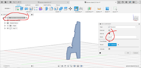
After setting the dimensions, we click create, and "new component" and name it "leg 1". Create a sketch and click on the Z-Y plane(vertical plane).
Create a sketch. select just the line, and draw out this figure below.
Make sure that the corners are all 90°. If there happens to be a corner that is not 90°, we can always use the perpendicular function and select 2 lines so that they will be in 90°
After which, we will press on the letter "D" and click on the top 2 lines of the shape, it will reveal the angle of the two lines, when left clicked, a box will come up, giving us the option of changing the angle or not. In this case, we will use the parametric that we have already set. Type in " angle" into the box, and the angle of 145° will be set for the 2 lines.
Next, we want to define the width of the surface of the phone stand. To do this, we will press the D key, and select steepest line, bring out the length of the line, left click, and use the parametrics to help us to define the length. We will use an equation for this. Type in "device_width+border+ply" and you should get something like this.
We will continue with the width of the resting place for the phone. Press D and select the line where the phone will sit. Bring out the length and type in "device_thickness+(ply*3)" and you should end up with something like this.
Press D and select the outermost left line and type in 20. Time to really make this a leg !! Draw a trapezium at the base of the shape and use the parameter of "angle" for the angle on the right and left of the trapezium. It should look like this:
It will look weird but don't worry!! The dimensions feature works wonders in making your design look sharp and accurate!!
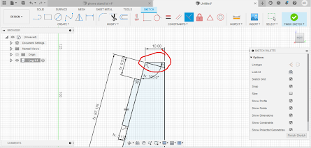
For the next step, press the D key and select the 2 points of the lines on the base(the start of the base until the start of the trapezium). Bring out the length and type in 10. do the same for the part AFTER the trapezium till the end of the base.
Next, press D and click on the top right point of the trapezium and then the bottom right of the trapezium and type in 20. Click the top line of the whole structure and type in 10. you should end up with something like this:
Next, click on the point then joins the steep line and its base and type in "device_width/2"
ADDING TABS TO HOLD THE DESIGN
Using the line function, draw 2 rectangles on the surface of where the phone is going to lean on and 1 tab at the base of where the phone will stand. Do not worry about the dimensions, but make sure that they are all 90°. You should get something like this:
We will then start defining our tabs. Press the D key and select the breadth of one of the tab and type in ply. Do this for all the tabs.
Press D and click the width of the tab of the base and click the most left outer line of the whole structure and type in "ply*1.5". Do the same for the inner part of the same tab
Moving on to the other 2 tabs, press D and click the length of one of the remaining tabs. Let it be 25mm, use the "equal" constraint and click the same line and also the other length line of the other tab so that they both are the same length.
Next, press D and click on the breadth of the lower tab and the base of where the phone will be sitting. Set that as "ply*3"
Do the same for the upper tab and the highest point of the whole structure.
In order for the top of the structure to be smooth and not dangerous to anybody, we would wanna shave off the top of the structure. Hence we will use a line, connect the top and draw a line to the right side of the structure. Be sure to use the perpendicular constraint.
Once done, finish the sketch and EXTRUDE and click on the parts that we want for the thickness, type in "ply".
Then we will activate the top component, create a new component and name it leg 2.
CREATING THE SECOND LEG
From here, click on construct, then click on offset plane. Then, click on the origin plane.
Then type in "-device height"
Create a sketch and click on the plane that has just been created. Use the "project" function by pressing P on the keyboard. Select the whole body of the drawing and finish sketch.
Extrude the figure and type in "-ply"
CREATING THE TRAY
Create a sketch, and click on the small face of the place where the tray is going to fit in.
Press the P key and select the places where the tray is going to fit in.
Once projected, there will be dots that are created on the points of the rectangles that are chosen. Press the R key to draw a rectangle. Do not worry if it is off.
Using the collinear constraints, click on the top of the rectangle and either of the top of the lines that are projected such that the rectangle are passing through the points.
Press D and select the length of the projected rectangle and the drawn rectangle and type in "border".
Do the same for the other side and finish sketch.
CREATING THE TOP
Click extrude and select everything except for the tabs. Right click on the title of the project and create a new component. name it "top"
Next, create a sketch and click on the top front face of the right leg. Press P and select the all the faces of the front of both legs.
Press P again and select the FRONT of the tray. Press R and draw a rectangle. Again, don't worry about dimensions.
Using collinear constrains, the top line of the rectangle should be in line with the top points while the bottom rectangle should be in line with the second last points.
to make our sketch fully defined, we need to add dimensions. Press D and make the distance between the left side of the rectangle and the point to be the parameter "border". Do the same for the right side.
Finish the sketch and extrude. Select the board and the tabs ONLY. Set the distance to be "ply"
CREATING THE BRACE
Right click on the main section and create a new component. Name it Brace. Create an offset plane and click on the back surface of one of the legs. Set it -5mm.
Then, create a sketch right on that plane. Press P and select the outer face of the back of the legs.
draw a rectangle such that the breadths of the rectangle is in line with the outer lines of the selected faces.
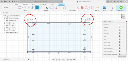
Select the midpoint constraint, click on the breadth of the rectangle and the outer line of the leg. This will ensure that the rectangle is in the middle. Set the dimension of the breadth of the rectangle to be 20.
After that, draw small rectangles on the inner side of the rectangle. Set the breadth of the small rectangle to be 5, the length to be "ply" and the distance between the top of the small rectangle to the length of the bigger rectangle to be 7.5. Do the same for the other side.
Finish our sketch and extrude. Select everything but the tabs. Set the direction to be extruded "symmetric" and distance to be "ply/2".
After that, click on the main project at the top and activate it. Click combine, target body is the leg, and the tool body is the brace. Operation is cut, and tick the "keep tools". Do it for both legs.
FILLETING
We wouldn't want out product to cut people and be a danger to everyone, therefor we must fillet the sides and also the tabs such that it is smooth to fit it in the parts too.
Click fillet and click on the edges of all the tabs, give it an edge of 0.1mm. And for the rest of the edges, give it a fillet of 2mm. Do for the other leg as well.
Activate and isolate the tray, fillet the front corners 5mm, and the back corners 0.1mm
Activate and isolate the top and fillet the top corners 5mm and the lower corners 0.1mm
AND THERE YOU HAVE IT!! Your very own phone stand !!!!
Through this I learnt that its never easy to learn something new. Its challenging at first but once you get the hang of it, it should be a breeze. When i first embarked on doing this design, it was challenging because I was not really creative. And for me to think of a phone stand design with an app that i am unfamiliar with, I felt that it was impossible. Fortunately, with the help of youtube and some Fusion 360 basics, I finally got the hang of it. What seemed like hours to do at first only took me 50 mins to redesign the whole design. I learnt that I shouldn't see learning new things as an obstacle but rather a chance to explore new things and broaden my knowledge and creativity rather than sticking to the conventional way of learning.


Comments
Post a Comment